Hello FollowFox Community!
In this series, we will start from scratch - an empty canvas of ComfyUI and, step by step, build up SDXL workflows. Together, we will build up knowledge, understanding of this tool, and intuition on SDXL pipelines work. Here is the rough plan (that might get adjusted) of the series:
So in this post, I’ll try to understand this tool better and take you along with me on this journey.
In this series, we will start from scratch - an empty canvas of ComfyUI and, step by step, build up SDXL workflows. Together, we will build up knowledge, understanding of this tool, and intuition on SDXL pipelines work. Here is the rough plan (that might get adjusted) of the series:
- In part 1 (this post), we will implement the simplest SDXL Base workflow and generate our first images
- Part 2 - (coming in 48 hours) we will add SDXL-specific conditioning implementation + test what impact that conditioning has on the generated images.
- Part 3 - we will add an SDXL refiner for the full SDXL process
- Part 4 - this may or may not happen, but we intend to add upscaling, LORAs, and other custom additions.
So in this post, I’ll try to understand this tool better and take you along with me on this journey.
Getting Started and Overview
ComfyUI (link) is a graph/nodes/flowchart-based interface for Stable Diffusion. To get started, check out our installation guide using Windows and WSL2 (link) or the documentation on ComfyUI’s Github.
Stable Diffusion is a Text to Image model, but this sounds easier than what happens under the hood. Many steps occur between the input (text) and the output (image) that we do not see or pay attention to. The original SD models had at least three parts:
- Text Encoder takes user text input and turns them into a specific combination of numbers that the model can understand. This text encoder part of the model for SD is based on CLIP models, and that’s why it is sometimes referred to as CLIP.
- UNET - the main part of the model that starts with noise (some combination of numbers and combination of numbers from text encoder) and turns that noise into another combination of numbers that can be turned into an image
- VAE - a model that takes those number combinations and turns it into a visual image. VAEs can also do the opposite and turn an image into the numbers we discuss.
All of these parts of the model need to talk to each other, and, at the same time, there is a long list of parameters that we can control for each step to instruct these models on how to operate.
If that is not complex enough, the SD community has been doing an amazing job of adding a ton of pre and post-processing workflows to the image generation process. The simplest example would be an upscaling workflow where we have to load another upscaling model, give it parameters and incorporate the whole thing into the image generation process.
And finally, SDXL decided to make all of this slightly more fun by introducing two-model architecture instead of one. So in many parts of the process, the number of communications and parameter choices that need to occur have doubled. We have been staring at those scary spaghetti nodes from ComfyUI.
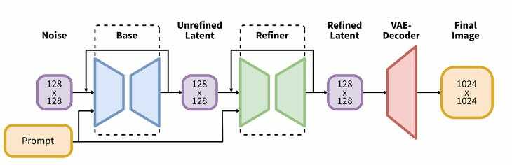
If we look at the illustration from the SDXL report (link) - it resembles a lot of what we see in ComfyUI. Different parts of the image generation process are connected with lines. And that’s exactly what ComfyUI does - it visually compartmentalizes each step of image generation and gives us levers to control those individual parts, and lines to connect them.
After the long overview, let’s start our exploration.
Let’s Build Our First Image Generator Flow (Base SDXL)
Before proceeding here, make sure to generate a couple of images using existing, preset workflows. That should give you a sense of where we are heading.
Our first goal is to start from scratch and build a simple workflow that generates images using SDXL. The goal is to keep it as simple as possible to achieve a functional thing that will be a starting point to go deeper. So no refiner or anything fancy here.
Knowing how Stable Diffusion works, we can roughly plan what will be needed here:
- A node where we will input a text
- A node that will load the model with all three parts
- A node that will encode the text (turn it into numbers)
- Some sort of sampler that will run the UNET (create the image)
- A decoder that will turn numbers from UNET into an image
- And a space to display the image
Load Checkpoint
Let’s start with loading the model and building around it. We will start with an empty canvas; you can do this by opening ComfyUI as usual and then pressing the “Clear” button.
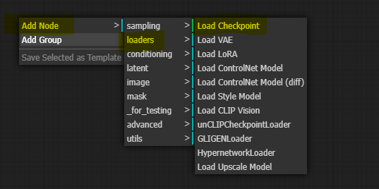
To add the first node, right-click anywhere and select the desired node. In this case, we will select the Load Checkpoint node.
A simple node appears that allows us to select the model and connect things around it. Let’s look closer at this one since it is our first node.
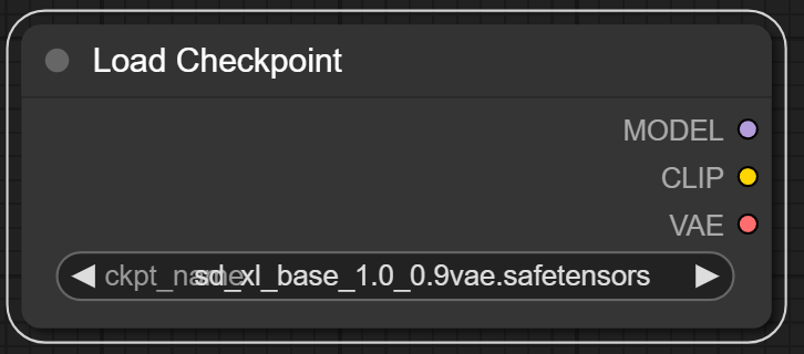
Clicking on different parts of the node is a good way to explore it as options pop up. On the top, we see the title of the node, “Load Checkpoint,” which can also be customized.
At the bottom, we see the model selector. This will display our checkpoints in the “\ComfyUI\models\checkpoints” folder. In this case, we selected “sd_xl_base_1.0_0.9vae.safetensors”.
On the right hand, we see three output slots, each representing the three individual parts of the SDXL Base model, as we discussed earlier.
Add Sample for the Model
As the next step, let’s proceed with a sampler since the “Model” purple slot is the first of the three in the model loader. You can think of the sampler as the main engine in this process that connects everything and pulls and pushes most of the things needed for image creation.
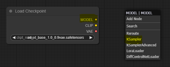
So if you left-click the MODEL output slot (purple dot) and drag it to any part of the canvas, it will give you a few options to add nodes connected to it. The dropdown list suggests a few initial top choices, and for more advanced users, you can select from the full list by pressing “Add Node.” We will add a top suggested “KSampler” node in this case.
Let’s take a close look at the Sampler node, as this will inform a lot of what else we need to build around it.
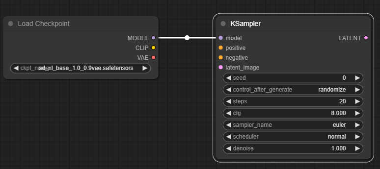
As we can see, on the left side, it has four input slots:
- Model - already connected to the loader Model that loaded UNET
- Positive and Negative slots: here, we must connect encoded positive and negative prompts. Since all these slots are required, we must build negative and positive inputs to encode.
- Latent image - as discussed before, UNET starts with a random staring image, so we will have to feed it to this pink slot.
Then, at the bottom, we see a bunch of parameters that we can control:
- Seed - the seed number used for the process
- Control after generate: this affects the seed number above. For example, switching this to fixed will keep the seed number above consistent.
- Steps - number of steps we will be using
- CFG - same as automatic1111. Basically, this controls the ratio between the text converted to number format and the random starting image.
- Sampler name, scheduler, and denoise - all parameters controlling the image generation process and allow you to use some popular implementations.
Finally, on the right-hand side, we see a pink output Slot. This will be our image that can be passed to VAE to Decode it in image format.
Positive and Negative Prompts and Text Encoding
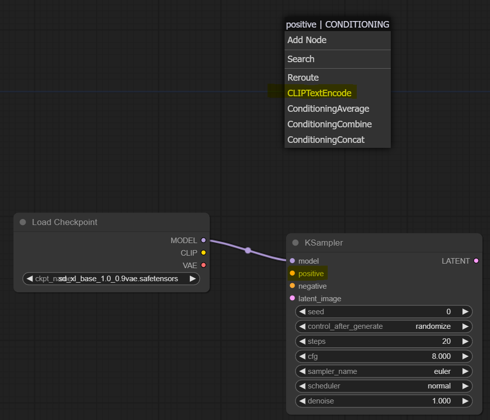
Let’s continue by adding positive and negative prompts as the Sampler requires. Like last time, let’s left-click on the orange “positive” slot and drag it upwards anywhere on the canvas. Then from the dropdown, we select the “CLIPTextEncode” node. Then we repeat the same for the orange “negative” slot to add another node for negative prompts.
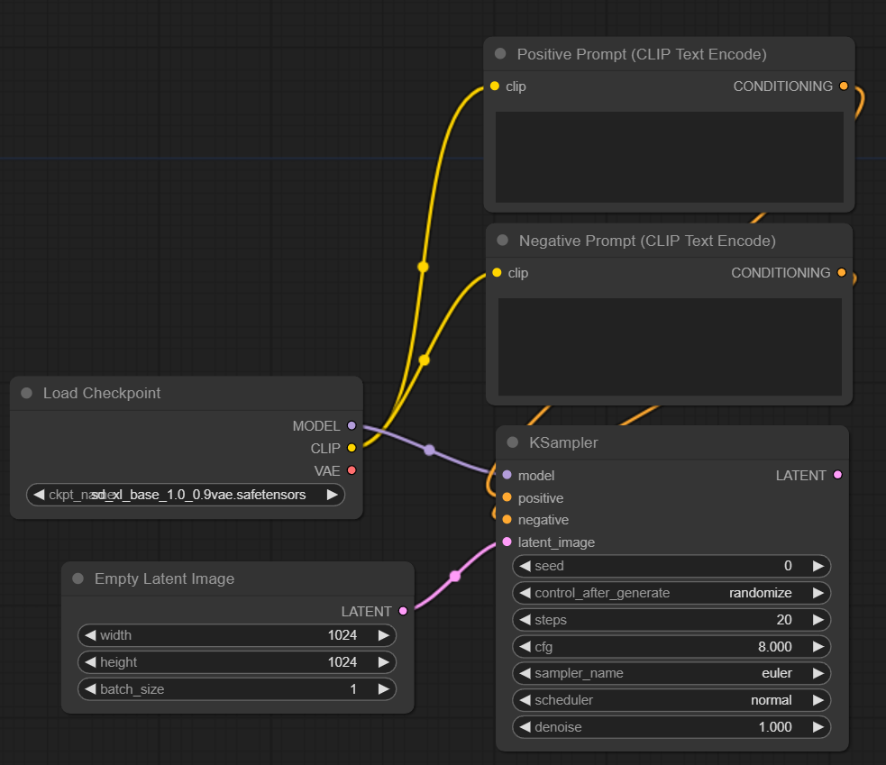
We will end up with two new nodes. We renamed them to ensure we don’t confuse which one is which in the future (right clock on the node and press “Title”). Now sampler is connected to these two on the right-hand side with the orange nodes. However, on the left, we see two unconnected slots called “clip.” These are for the CLIP model; we connect that to the CLIP slot in the model loader. Reminder that CLIP is the text encoder part of the model, so the loader node has loaded it for us, and we connect it to the text encoding node to use it. In the end, we should end up with something like this:
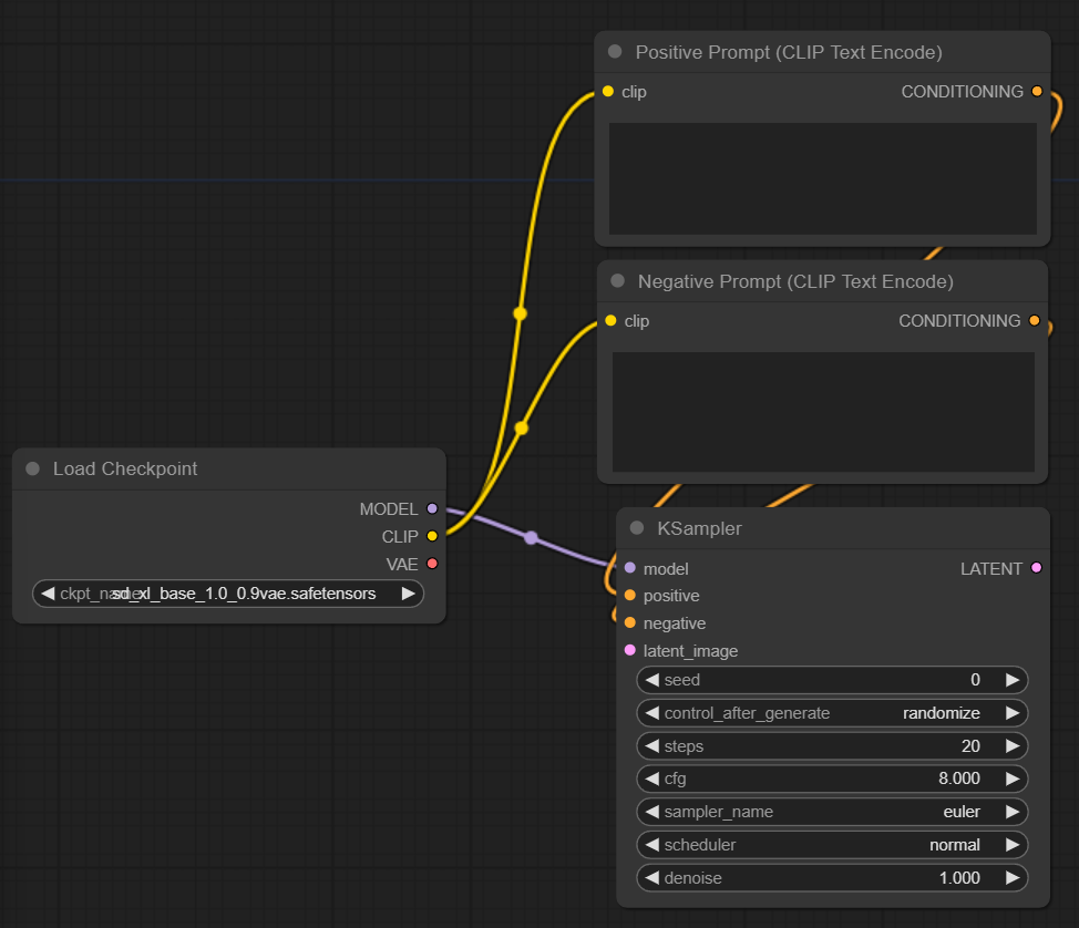
At the bottom, we have a text input for each node where we can add our prompt.
Adding Latent Image Node
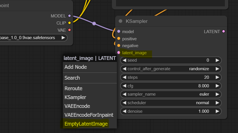
If we return to our KSampler, we have one remaining unconnected pink slot on the left side called latent_image. In this case, we will connect this to an empty starting image. However, to develop our intuition, you can imagine connecting this to the latent representation of an existing image, and by doing so, we are switching the workflow tom Image to Image.
As usual, left-click the pink “latent_image” slot on KSampler and drag it anywhere on the canvas. Then select “EmptyLatentImage” node.
As you can see, it is a very simple node with three parameters and one left-side output slot already connected to the sampler. Let’s change the width and height parameters to 1024x1024 since this is the standard value for SDXL.
VAE and Displaying the Image
Our KSampler is almost fully connected. The only unconnected slot is the right-hand side pink “LATENT” output slot. This is where we will get our generated image in ‘number’ format and decode it using VAE.
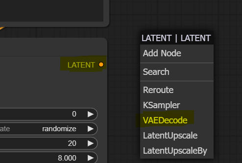
Left-click the pink “LATENT” slot on KSampler and drag the mouse cursor to anywhere on the canvas. Then select the “VAEDecode” node.
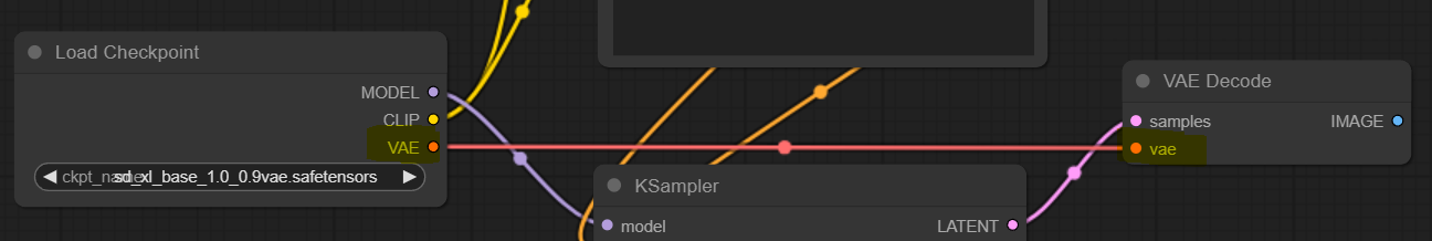
The new node has two unconnected slots. On the left side, we see a red input node called “vae,” we connect this to our Load Checkpoint node’s left-hand side output red node called “VAE.”
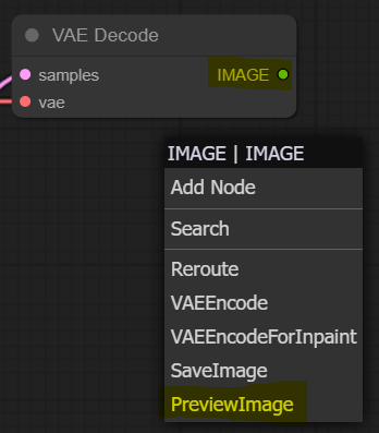
Let’s deal with the last unconnected slot, the blue right-hand side slot called “IMAGE” on our VAE Decode node. Left-click on it, drag it to the canvas, and add “PreviewImage” node.
Congrats! Now we have a full loop that should enable us to generate images using SDXL base model. You should have something like this if you followed along.
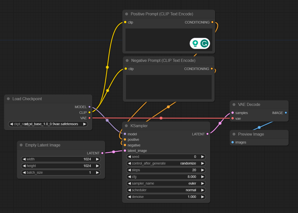
Generate some images
This is the simplest part - enter your prompts, change any parameters you might want (we changed a few, highlighted in yellow), and press the “Queue Prompt” button. You will see which nodes are being activated in what order, and in a few seconds, you will have your first SDXL image generated.

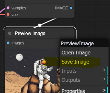
You can save the image by left-clicking on it.
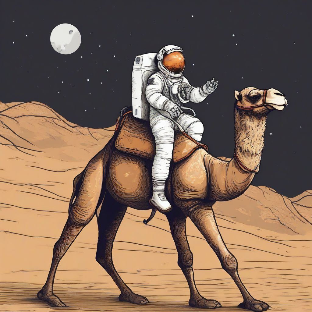
And don’t forget one of the coolest features of ComfyUI - you can drag any image generated by anyone in ComfyUI on the canvas, and it will load the original setup used for generating that image. You can try this one.

Save this image, drag it on ComfyUI canvas, and the workflow will load
Note: if the image doesn’t work due to a Substack format change, download it directly from this link.
Stay tuned for part 2, where we will implement SDXL conditioning workflows!
Stay tuned for part 2, where we will implement SDXL conditioning workflows!
