Hello FollowFox Community!
Welcome to the final part of the ComfUI series (for now), where we started from an empty canvas and have been building SDXL workflows step by step. The goal is to build up knowledge, understanding of this tool, and intuition on SDXL pipelines.
In this post, we will modify our workflows to accommodate a few more advanced stuff, but more importantly, from here, you should be able to navigate the tool well and build out any workflows you might need.
Let’s take a look at our journey so far:
- In part 1 (link), we implemented the simplest SDXL Base workflow and generated our first images
- Part 2 (link)- We added SDXL-specific conditioning implementation + tested the impact of conditioning parameters on the generated images.
- Part 3 (link) - we added the refiner for the full SDXL process.
- Part 4 (this post) - We will install custom nodes and build out workflows with img2img, controlnets, and LoRAs.
Custom Nodes and ComfyUI-Manager
Custom nodes are what make Comfy extra powerful. They introduce new functionalities to tools ranging from more advanced control on certain aspects to doing some totally new stuff. In a way, this is equivalent to Automatic1111s extensions. Comfy’s community has been quite active in developing these. Covering all available custom nodes is impossible, but we will use a few in this post.
Custom nodes could be installed one by one via their sources, but that’s quite tedious. Luckily, there is a tool that allows us to discover, install, and update these nodes from Comfy’s interface called ComfyUI-Manager (link). So, let’s start by installing and using it.
Installing ComfyUI-Manager
In general, it is very easy. If you are using our WSL2 installation (link), you can follow these steps, and if not, just check their Git Hub.
- Launch WSL2 and activate the environment: conda activate comfy
- Go to the custom_nodes folder: cd ComfyUI/custom_nodes/
- Clone the repo: git clone https://github.com/ltdrdata/ComfyUI-Manager.git
- Launch Comfy as usual, go back to the main folder cd .. and then python main.py
Now, in the WebUI, we see a new button called manager.
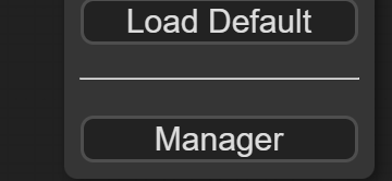
Clicking it brings up the Manager window with a few interesting functionalities, but we will focus on the Install Custom Nodes part for now.
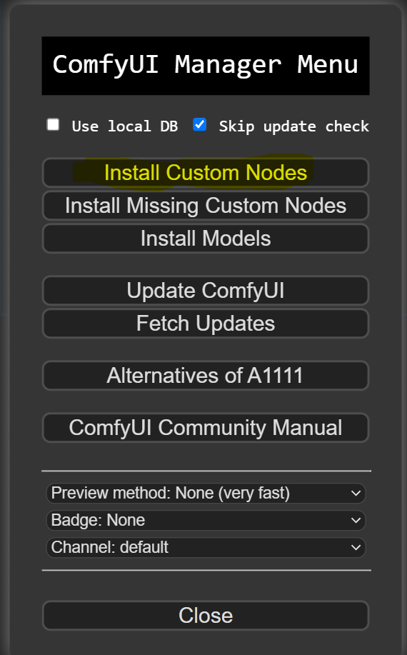
As you can see, there are well over a hundred custom nodes, and you can explore and install them by simply clicking the install button. For this post, let’s install the following four nodes, and we will explore them a bit later.
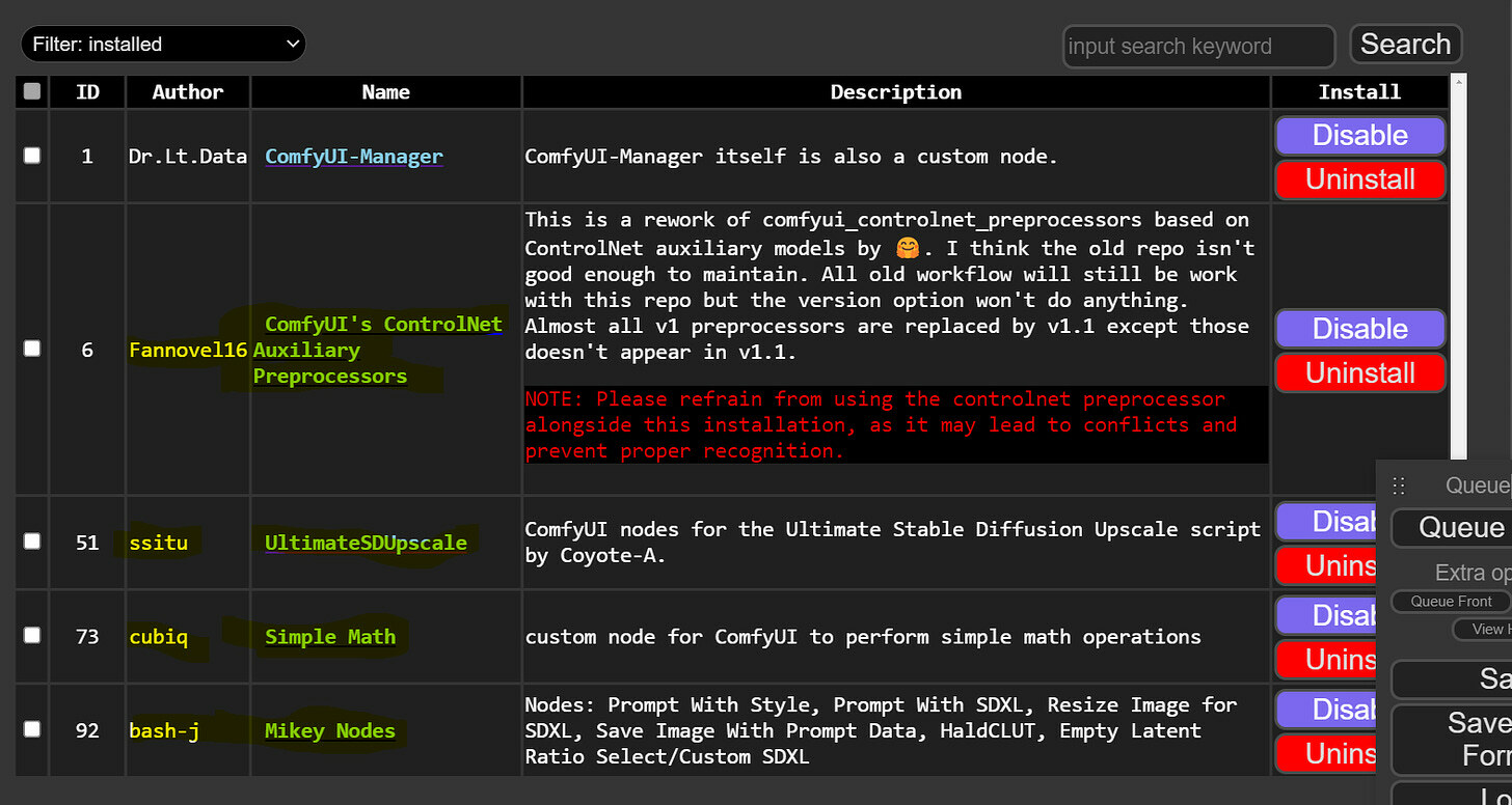
Image to Image with SDXL
As usual, we will start from the workflow from the last part. You can load it by dragging this image to your ComfyUI canvas (link).
Changes to the previous workflow
There are a few updates that we found are convenient to set up differently, so let’s do that.
CFG, Steps, and Seed Number
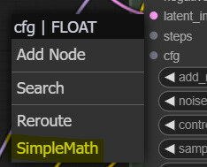
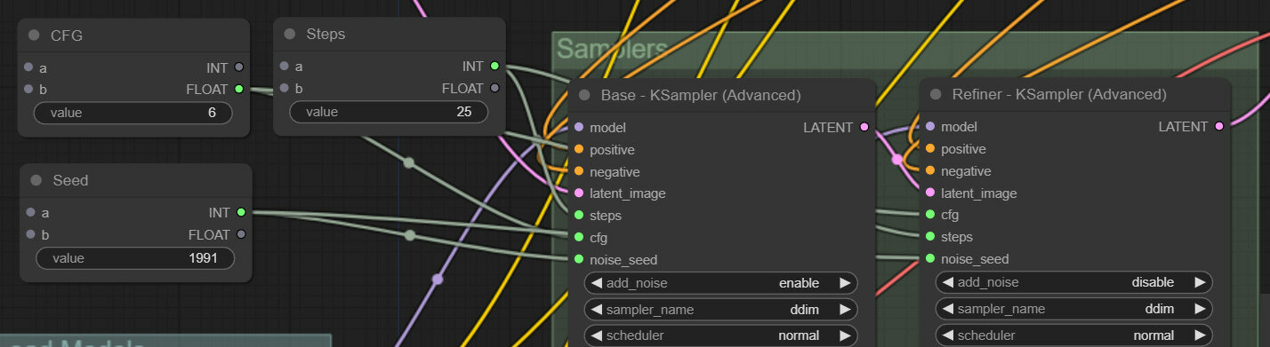
First of all, steps, CFG values, and seed numbers are something that we have been changing a lot, and since these values need to be in sync for both the base and the refiner samplers, there is no need to input them separately. Let’s turn these six input slots into inputs (3 on base and 3 on the refiner) by right-clicking the samplers. Now, left-click the newly converted steps input slot, drag it on the canvas, and we will select the SimpleMath node, which is one of the custom ones we just installed.
Change the title of this node to CFG and just input the value in the entry form. To make it look cleaner, you can convert a and b to inputs (we are not using them here). Do the same for steps and seed, connect both samplers, and we are done. It should look like this.
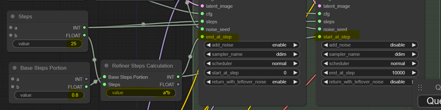
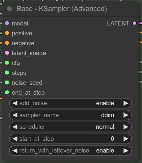
Another annoying thing we have been dealing with is syncing start_at_step and end_at_step values for the two refiners. If you think about it, the two values are synced and change depending on the total steps and the portion of steps we want to do with the refiner. The starting step for the base always needs to be 0 for text2image, so we don’t touch that, and the ending step for the refiner always has to be equal or higher than the target steps, so we don’t touch that either and just leave it with a very high value. So, let’s convert end_at_step on the base sampler to input and do the same for start_at_step for the refiner sampler.
Next, we will create two SimpleMath nodes. The first one will be similar to the previous ones, and here, we will input what portion of the steps should be done with the base model. So, we changed the node's title accordingly and set the value to 0.8 for now. In the second node, we will finally do some math. As an input, it will take out the value of the step from the previous node that we set to 25, and the second input will be the just-created Base Steps Portion value. Then, we will multiply the two numbers by writing the formula a*b (a slot multiplied by b slot). In this case, this results in 25*0.8=20. We will use this value as steps for the base Sampler and starting steps for the refiner.
Next, we will create two SimpleMath nodes. The first one will be similar to the previous ones, and here, we will input what portion of the steps should be done with the base model. So, we changed the node's title accordingly and set the value to 0.8 for now. In the second node, we will finally do some math. As an input, it will take out the value of the step from the previous node that we set to 25, and the second input will be the just-created Base Steps Portion value. Then, we will multiply the two numbers by writing the formula a*b (a slot multiplied by b slot). In this case, this results in 25*0.8=20. We will use this value as steps for the base Sampler and starting steps for the refiner.
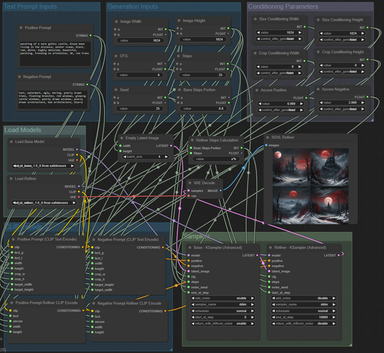
Next, we realized that Aspect Ratio Conditioning performs better when kept in sync with the image size you intend to generate. So, we will remove the two aspect ratio conditioning nodes, create two new SimpleMath nodes for intended image width and height inputs, and connect those to the EmptyLatent node and the corresponding nodes on CLIP encoders. So, we create two SimpleMath to input width and height; each will connect to five nodes.
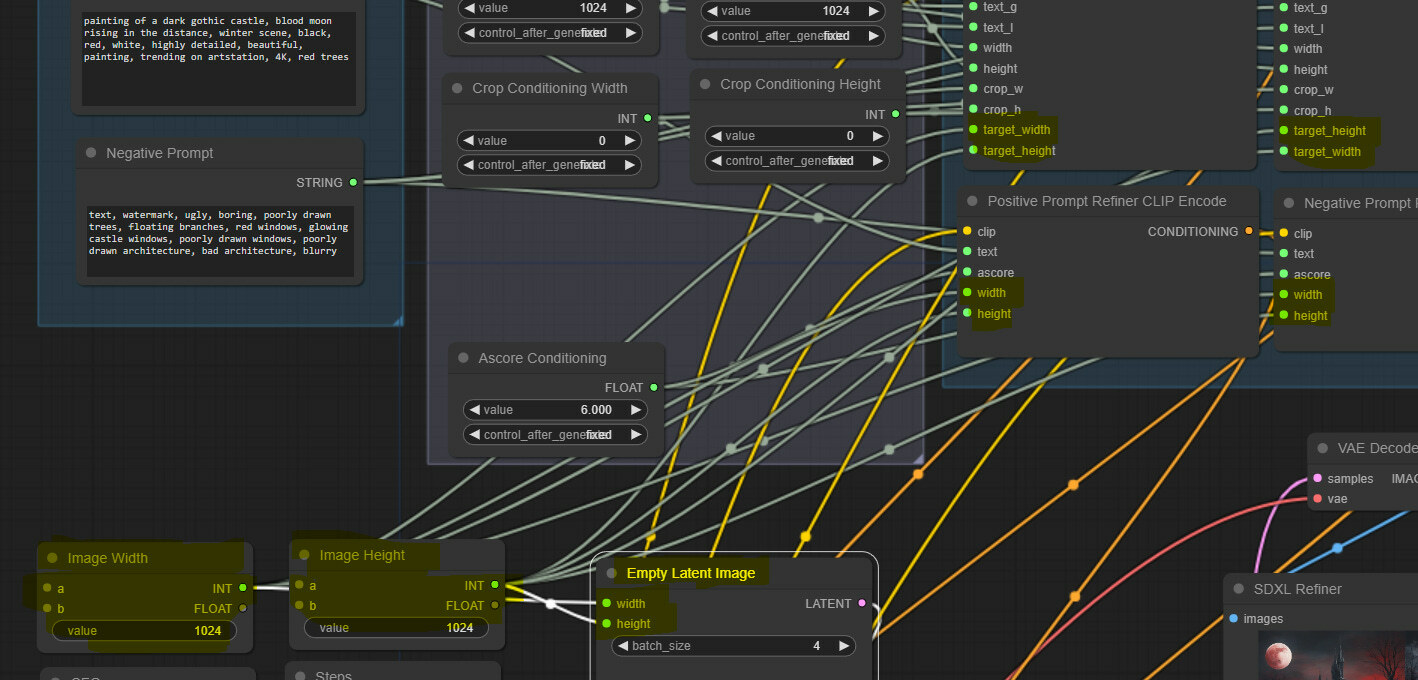
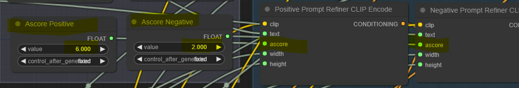
This is minor, but some resources suggest using low Ascore conditioning values for negative prompts with the refiner, so we clone the ascore conditioning node, rename it, and connect accordingly.
To finish upgrading our workflow, we logically regroup nodes and get a workflow that looks like this.
You can download and use this workflow with this image (link).
Adding LoRAs
Adding LoRAs to the workflow is relatively simple, and we found finding the right strength values, especially if using multiple LoRAs, much trickier.
For this testing purposes, we will use two SDXL LoRAs, simply selected from the popular ones on Civitai. Pixel Art XL (link) and Cyborg Style SDXL (link). Download the files and place them in the “\ComfyUI\models\loras” folder.
Let’s start by right-clicking on the canvas and selecting Add Node > loaders > Load LoRA. We get a new node looking like this.
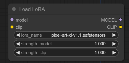
As we can see, its input slots will connect to the Load Base Model’s and clip output slots. Then the LoRA is applied to both by selecting the LoRA model and strength for both UNET (model) and CLIP. After that, we can connect the MODEL output slot to the base KSampler and the CLIP output slot to Positive and Negative Text Encode nodes (base ones only). So, let’s do that and see how before-after images compare with the LoRA.

The LoRA is definitely being applied. So, let’s improve our workflow a bit. One LoRA is good, but six gives a ton more convenience! Also, instead of the standard LoRA loader, we will use one from the Comfyroll custom nodes, as it allows us to switch the LoRAs on and off. Thus, we don’t need to delete the strength values every time we want to disable it (Add Node > Comfyroll > IO > CR Load LoRA). We add six of them and title them accordingly. The first one will be connected to the Load Base Model, then we will chain connect these six nodes, and finally, we connect the last node to the base KSampler and Positive and Negative Text Encode nodes. It should look something like this after some cleanup.
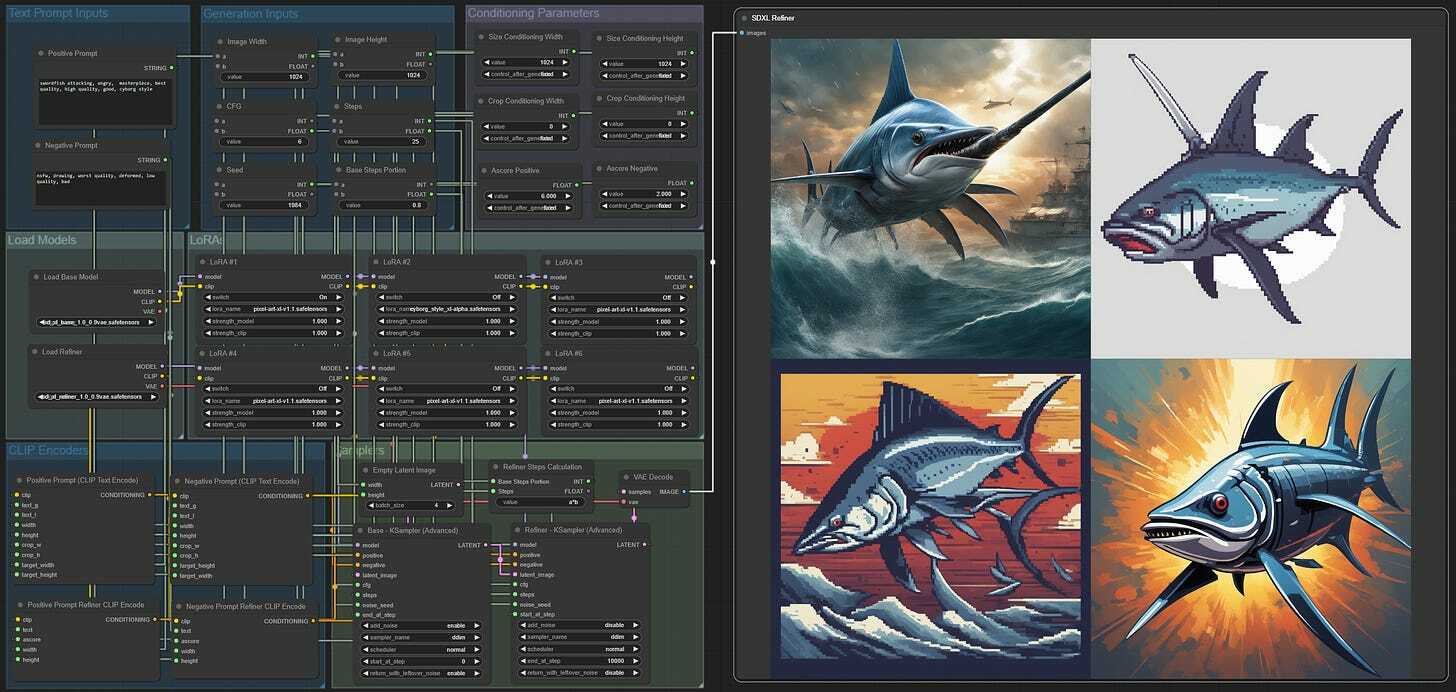
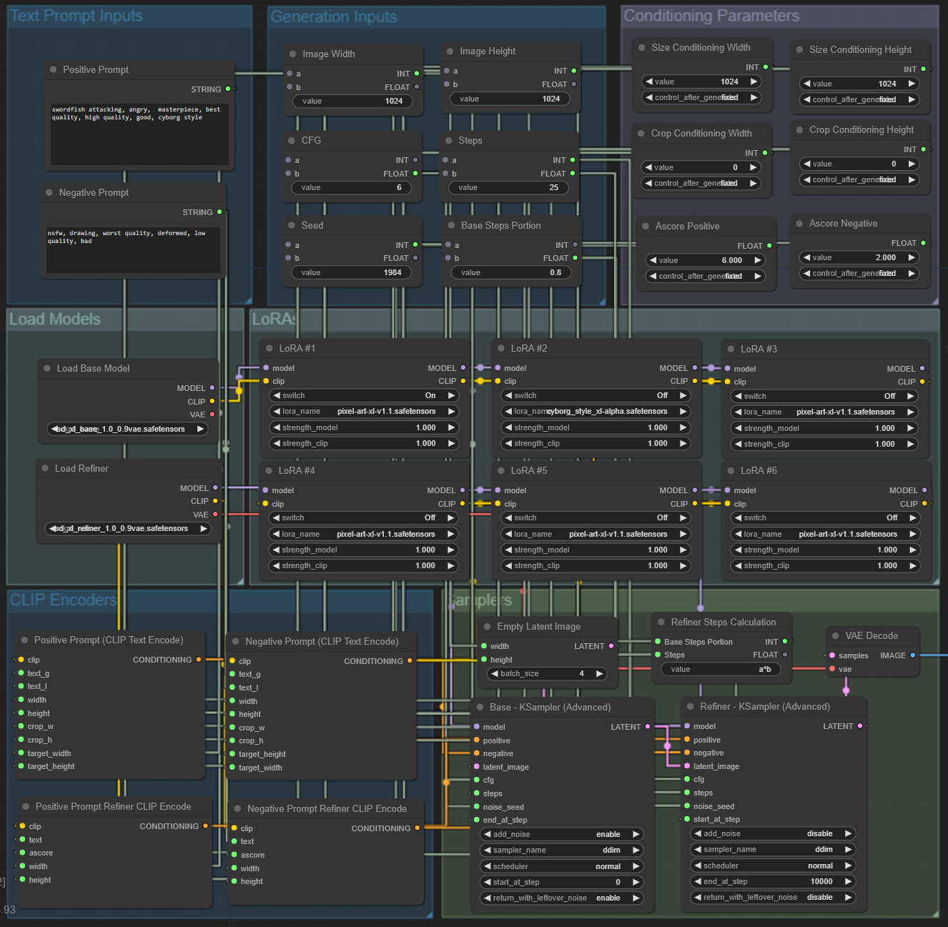
Note: We use spline lines when building the workflow and switch to linear for a cleaner view once it’s built.
You can download this image to load the workflow with LoRAs (link).
Image to Image in SDXL
This ended up a bit more complex than we expected. Intuitively, we just need to replace empty latent input on a base sampler with a latent representation of the image we want to use, apply denoise percentage, and that’s it. However, if we examine the advanced KSampler, we see no way to input denoise values.
At first, we thought this was a mistake, but soon, we realized this was intended - adding the start/end at step inputs made the denoise input obsolete. Turns out that skipping the first steps is equivalent to applying the denoise value. What happens is that the total step count schedules the amount of noise that will be added and removed to the starting image, and skipping initial steps means reducing those amounts. So, if we input 60 steps and skip the first 30, that would be equivalent to doing 60 steps with a 0.5 denoise value. In fact, that’s how it has always worked, and if you try to set a low denoise value in Auto1111, you will observe that the steps executed are also very low.
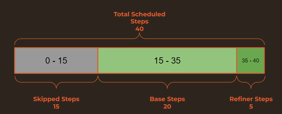
This all gets confusing with the refiner since we already have calculations that impact starting and ending step points. Let’s discuss this with an example. So far, for txt2img, we have been doing 25 steps, with 20 base and 5 refiner steps. Let’s say we want to keep those values but switch this workflow to img2img and use a denoise value of 0.75. That means we will have to schedule 40 steps (25/0.75=40) and skip the first 15 steps.
This all gets confusing with the refiner since we already have calculations that impact starting and ending step points. Let’s discuss this with an example. So far, for txt2img, we have been doing 25 steps, with 20 base and 5 refiner steps. Let’s say we want to keep those values but switch this workflow to img2img and use a denoise value of 0.75. That means we will have to schedule 40 steps (25/0.75=40) and skip the first 15 steps.
Now, let’s try to implement all of this in ComfyUI.
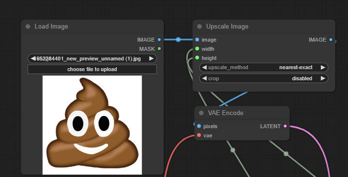
Right-click anywhere on the canvas and select Add Node > image > Load Image to add the image loader node. Next, we will resize the input image to match our generation size. For this, Add Node > image > upscaling > Upscale Image. Connect the image input slot to the image loader, then convert the width and height to input slots and connect to Image Width and Image Height nodes accordingly. For now, keep the crop disabled and the method “nearest-exact.”
Next, we will convert this image into a latent version. Left-click on the IMAGE output slot from the upscaler, drag on canvas, and create the VAE Encode node. Connect the vae input slot to the base model loader and the LATENT output slot to the base KSampler.
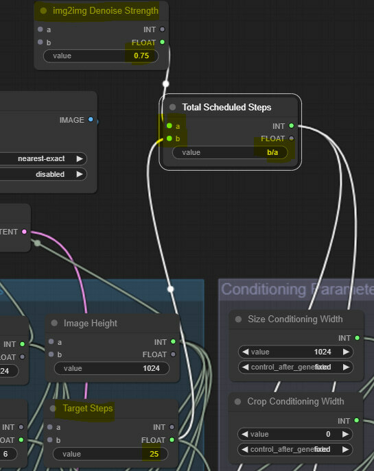
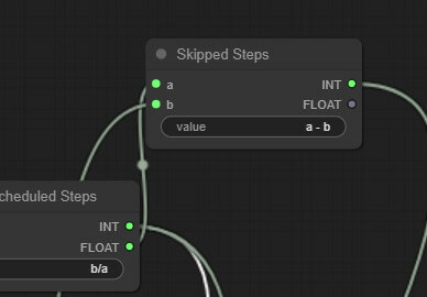
Time to do some simple math! Let’s create a Simplemath node, call it img2img Denoise, and input 0.75 as a value. Then, create another Simplemath node and call it Total Scheduled Steps, as we showed on the graph. We will connect the first input slot to the just created img2img Denoise node and the second b input slot to the target steps (previously just steps) node in the generation Inputs group. We calculate the total steps in the value by entering b/a (in this case, 25/0.75 = 40). The output slot from this node will connect to both samplers as steps input value.
Now, let’s calculate the skipped steps count. We create another Simplemath node and call it Skipped Steps. We connect the “a” input slot to the Total Scheduled Steps and the “b” input slot to the Target Steps node. We calculate skipped steps by entering a - b (in this case, 40-25 = 15). We connect the output slot of this node to the start_at_step slot (convert it) of the base KSampler.
Now, we need to tell the base sampler where it needs to stop and the refiner where to start (in this case, step 35 for both). Let’s create another Simplemath node and call it Base Sampler End. Let’s connect the Skipped Steps INT slot to the “a” input slot and the “b” input slot to the Refiner Steps Calculation node from the earlier section. Enter the formula a+b (15+20 = 35) to get the desired value. Output of this calculation will be connected to the end_at_step slot of the Base KSampler and the start_at_step slot of the refiner KSampler.
Please note that this implementation might need high values in Denoise Strenght's input to change the image substantially. Don’t treat it as a portion that changes from 0 to 1; you should expect that different values will work depending on the scheduler selected.
After some cleanup, here is our Image-to-Image workflow. You can simply download this image as usual (link).
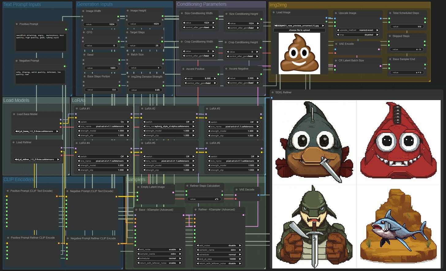
Image to Image in SDXL
We will keep this section relatively shorter and just implement canny controlnet in our workflow.
Let’s download the controlnet model; we will use the fp16 safetensor version (link). Then move it to the “\ComfyUI\models\controlnet” folder. We name the file “canny-sdxl-1.0_fp16.safetensors”.
Now in Comfy, from the Img2img workflow, let’s duplicate Load Image and Upscale Image Nodes. Connect the upscale node’s input slots like previously.
Now let’s add out the Canny pre-processor: Add Node > ControlNet Proprocessors (this is a custom node) > Line Extractors > Canny Edge. Connect the image input slot to the Image output slot of the upscaler node.
Next, load our controlnet model: Add Node > loaders > Load ContolNet Model. For now, just select the canny model and leave this node as is.
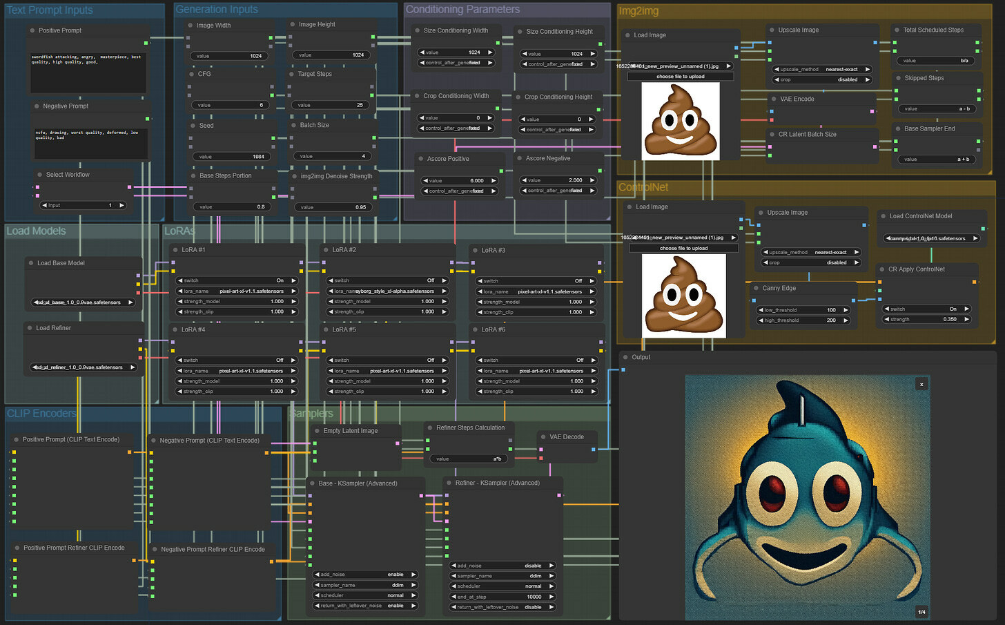
We continue by adding the node that will apply the controlnet. Add Node > Comfyroll > Conditioning > CR Apply ControlNet. We connect the image input slot to the Canny Edge Preprocessor. Control_net input slot the controlnet loader node. Conditioning input to the CONDITIONING output slot from the Positive Prompt (CLIP Text Encode) node. Finally, the CONDITIONING output slot must be connected to the base KSampler positive input slot. In the end, the added nodes look like this:
Experiment with different controlnet models, pre-processors, and the controlnet application strength values. Finding the optimal combo that works for your specific tasks typically takes time.
As always, we do some cleanup to arrive at the final workflow of this series. You can download it with this image (link).
Let us know what you think and propose any suggestions and improvements.
